I have many articles and notes from R.G. Sparber. I ran across one a few days ago that struck my fancy. It is a plan for an ID gage, taking the place of the standard telescoping gages.
Sparber made the body of his from steel, but the closest I have is aluminum. Two 2" lengths of 1/8 X 1/2" aluminum bar were cut with the hacksaw for the top and bottom plates of the gage. After milling to length the plates were marked out for the hole and for the slot.
The end of one plate was drilled on the marked spot with a center drill, a #24 drill, and a C drill. The hole was reamed with a 1/4" reamer. The same process was used to drill the two ends of the slot. Holes were then drilled every 1/4" to remove most of the material from the slot. The photo below shows the slot at this stage.

The drill chuck was switched for the collet with a two flute end mill installed. The end mill milled down through the small hole and then in both directions to finish the slot to width. Significant filing was needed to clean up the slot and allow a 1/4" sliding fit. The same process was repeated on the second bar of aluminum. One of the slotted bars had the end of the slot aligned with the spindle and countersunk with a 3/8" end mill to a depth of 0.050". The photo below shows the two completed blades.

Two pins were made from 1/4" drill rod. They were cut slightly longer than 5/8". First, one end was faced and then the opposite end was faced to length. Both ends were chamfered. The nut was made from a length of 3/8" drill rod. It was reduced to 0.250" for a length of 0.190". A heavy chamfer was filed on the corner of the remaining 3/8" stock. The part was drilled #36 and tapped 6-32. Then the nut was parted off at 0.235". It and the pins are shown below.

The final part to make was the knob. A length of 1/2" brass round bar was held in the chuck. The end was faced and heavily chamfered. The first 1/2" was knurled with a lot of cutting fluid. The rod was then drilled and tapped 6-32. A decorative slot was cut in the knurl and then the piece was parted off. It is shown in the photo below with a length of 6-32 threaded rod cut from a screw.

Assembly required loctiting a few parts together. The pins were glued into the 1/4" holes. The nut was glued into the countersink and the 6-32 threaded rod was glued into the nut. The glue-up is shown in the second photo below. The first photo below shows all of the completed parts.


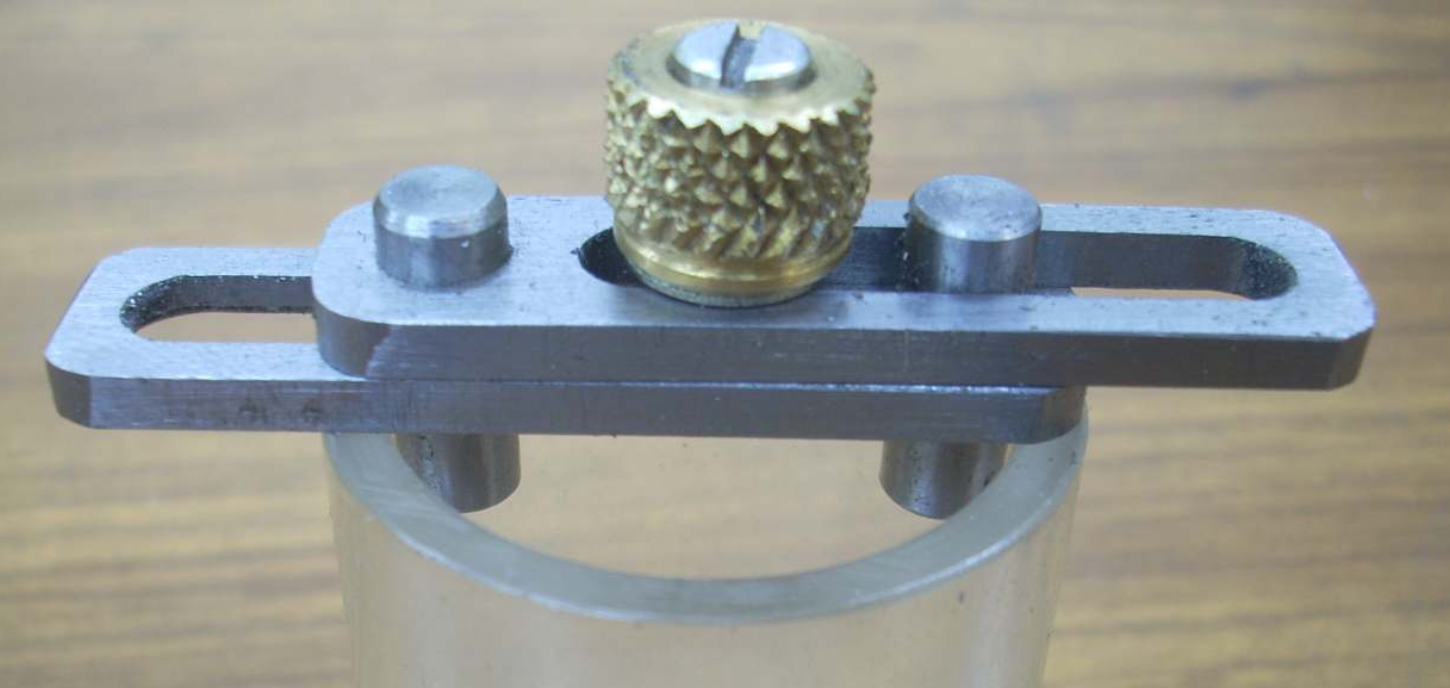
The gage was assembled this morning. With all three parts riding in the slots, the gage does not move freely and so the slots were filed giving a smooth movement. The photo below shows the assembled internal diameter gage. The gage will measure from 0.976" - 1.785".
